![]()
![]()

![]()


Please Call
(702) 324-6463
or email sales@nitevis.com
|
|
|
Categories |
||||||||||||||||||||||||||||||||||||||||||||||||||||||||||||||||||||||||||||||||||||||||||||||||||||||||||||||||||||||||||||||||||||||||||||||||||||||||||||||||||||||||||||||||||||||||||||||||||||||||||||||||||||||||||||||||||||||||||||||||||||||||||||||||||||||
Helpful Info
Export
Regulations
|

![]()
DEFINITIONS
![]()
A System Data Sheet is a document that will be included with some new Night Vision systems. Night Vision image tubes from L-3 Electro-Optics come with Tube Data Sheets. ITT no longer offers tube cards as of Jan 2007. Manufacturers must use a Hoffman Tester NVD Test Set ANV-20/20 in order to certify system performance. When deciding on a system, compare the numbers on this sheet to see which system is better. The terms used to compare systems are: photosensitivity, resolution, gain and signal-to-noise ratio. A higher number is better for comparison purposes
![]()
Performance The very need for Night Vision capability focuses on performance as the most important factor: Using Night Vision, can you see a clear image in the dark yet not see the same image with your unaided eye? Most Night Vision equipment available today will provide an adequate image under higher night-light conditions such as a full moon. Evaluate the following parameters to determine how well a system will perform when you need to see under truly dark conditions such as starlight.
Active Versus Passive High-performing Night Vision systems enable use in very low-light situations. No-light or extreme low-light situations (under dense foliage, in a cave or warehouse without windows) require additional illumination for optimal performance of the night vision device. IR illumination adds the needed light from the spectrum that is not visible to the unaided human eye. However, when IR illumination is in use (active), it can be seen by other Night Vision devices. You should select Night Vision equipment that will operate adequately without additional illumination (passive) in all but the most extreme conditions. Users also should use caution when operating the IR illumination in covert situations.
GAIN - Also called "Brightness Gain" or "Luminance Gain". This is the number of times a Night Vision device amplifies light input. The gain of a tube is measured in one of two possible ways. The most common way is cd/m2/lx or candles per meter squared per lux. The other way is to measure gain as Fl/Fc (Foot-lamberts over Foot-candles). This creates issues with comparative gain measurements since neither is a pure ratio, although both are measured as a value of input intensity over output intensity. This creates ambiguity in the marketing of night vision devices as the difference between the two measurements is effectively pi or approximately 3.14159 times. This means that a gain of 10,000 cd/m²/lx is the same as 31.4159 Fl/Fc. With a lack of convention on this item, if the units for gain are not specified, Fl/Fc should typically be assumed.
Gain is usually measured as tube gain and system gain. Tube gain is measured as the light output (in fL) divided by the light input (in fc). This figure is usually expressed in values of tens of thousands. If tube gain is pushed too high, the tube will be “noisier” and the signal-to-noise ratio may go down. U.S. military Gen 3 image tubes operate at gains of between 20,000 and 45,000. On the other hand, system gain is measured as the light output (fL) divided by the light input (also Foot-lambert fL) and is what the user actually sees. System gain is usually seen in the thousands. U.S. military systems operate at 2,000 to 3,000. In any Night Vision system, the tube gain is reduced by the system’s lenses and is affected by the quality of the optics or any filters. Therefore, system gain is a more important measurement to the user.
LINE PAIRS - a.k.a. line pairs per millimeter (lp/mm). This is a measurement of resolution. The more line pairs, the better the resolution. The best tubes are currently at 64+ line pairs.PHOTOSENSITIVITY - Photocathode sensitivity is a measure of how well the image intensifier tube converts light into an electronic signal so it can be amplified. The units of photocathode sensitivity are micro-amps/lumen (μA/lm), and is always measured in isolation with no amplification stage or ion barrier (film). It is the ability of the photocathode to produce an electrical response when subjected to light waves (photons). The higher the value, the better the ability to produce a visible image under darker conditions. A lumen is a scientific unit that measures light at wavelengths the human eyes see (violet through red). Since image intensifier tubes see light that the eye does not, it's important to know the spectral (color) content of the light used in testing photocathode sensitivity. Photocathode sensitivity is measured using a light source with a color spectrum similar to a theoretical black body operating at 2856°K (2856 degrees Kelvin). This light source was chosen because it has a color spectrum similar to the color of a night sky illuminated only by stars. Photocathode sensitivity measured with a different color spectrum light source will yield different readings.
RESOLUTION - or Limiting Resolution, this is measured as tube resolution (lp/mm) This is a measure of how many lines of varying intensity (light to dark) can be resolved within a millimeter of screen area. However the limiting resolution itself is a measure of the Modulation Transfer Function. For most tubes, the limiting resolution is defined as the point at which the modulation transfer function becomes three percent or less. The higher the value, the higher the resolution of the tube.
System resolution—is measured in cycles per milliradian (cy/mr). The more significant measurement is system resolution because this is what is visible to the user. Most systems produce an optimal resolution at some point between very high-light and very low-light conditions. As long as resolution is measured the same way using the same magnification and the same conditions (i.e., per U.S. military specs), then the higher the value, the better the ability to present a sharp picture. However, be aware that many devices will produce an image that is sharp in the center of the viewing area, but less sharp (or less defined) toward the periphery. Inability to obtain a clear, uniformly sharp image throughout the viewing area may be due to older technology (Gen 0, Gen 1 tube) or to the system’s optics.
The ability of an image intensifier or night vision system to distinguish between objects is measured in line pairs per millimeter (lp/mm). There is a difference between system resolution and image intensifier resolution. System resolution can be affected by altering the objective or eyepiece optics, or by adding magnification lenses. Image intensifier resolution remains constant. System resolution is very important in determining the quality of a system. Halo determines the glare effect with bright lights and is reduced dramatically in Gen 3+ image intensifiers because of their use of auto-gated power supply. The same system improves High Light Level resolution from 12 lp/mm in the latest 3rd generation image intensifiers to a minimum of 36 lp/mm.
An important consideration, however, is that this is based on the physical screen size in millimeters and is not proportional to the screen size. As such, an 18 mm tube with a resolution of around 64 lp/mm has a higher overall resolution than an 8 mm tube with 72 lp/mm resolution. Resolution is usually measured at the centre and at the edge of the screen and tubes often come with figures for both. Military Specification or MILSPEC tubes only come with a criterion such as "> 64 lp/mm" or "Greater than 64 line pairs/millimeter".
SIGNAL-TO-NOISE RATIO - S/R is a ratio of the magnitude of the signal to the magnitude of the noise. If the noise in the scene (see “scintillation” definition below) is as bright and as large as the intensified image, you cannot see the image. S/R changes with light level because the noise remains constant but the signal increases (higher light levels). The higher the S/R ratio, the darker the scene can be and the device still performs. The effect of S/R ratio in I2 devices is similar to that of a television far away from the TV station. At long distances from the station, the TV picture becomes noisy, and the ”snow“ blocks the picture. This criterion is tied with EBI (Equivalent Background Illumination) and illustrates the amount of interference (also known as “hazing” or “snow”) visible in extremely low light conditions. Since the absence of the ion barrier in generation 3+ tubes allows all electrons released from the photocathode to reach the amplification stage, it yields greater S/N ratio and lowers EBI with amazing performance in extremely low light conditions and dramatically reduced “hazing” in low light. The low light resolution of the image tube, the higher the signal-to-noise ratio, the better the ability of the tube to display objects with good contrast under low light conditions. It is the single best indicator of an image intensifier's performance.
Scintillation A faint, random, sparkling effect throughout the image area. Scintillation, sometimes called “video noise,” is a normal characteristic of microchannel plate image intensifiers and is more pronounced under low-light conditions. Do not confuse scintillation with emission points.
Equivalent Background Illumination (EBI)
This is the amount of light you see through a Night Vision device when an image tube is turned on but no light is on the photocathode. EBI is affected by temperature; the warmer the night vision device, the brighter the background illumination. EBI is measured in lumens per square centimeter (lm/cm2). The lower the value the better. The EBI level determines the lowest light level at which an image can be detected. Below this light level, objects will be masked by the EBI.Gating
Gating is a means by which an image intensifier tube may be switched on and off, like an electronic gate. In this respect, the term is the same as used in electronics. Due to the high speed with which image intensifier tubes can be gated, with speeds commonly measured in nanoseconds or even picoseconds, image intensifier tubes are commonly used in research environments where fast events must be photographed. Gated image tubes have been used for such purposes to see the wavefront of burning fuel in an internal combustion engine, allowing better combustion chamber design. Because of the very high speeds with which the shutter may be operated, combined with a light amplification capability, Gated image tubes can even see the travel of light. It is possible to fire a pulsed beam of light at a target and only capture the light reflected from that target by controlling the "gate" shutter to only allow light in that would have returned from the original pulse. Gated-pulsed-active Night Vision devices use this technique, which allows objects to be seen behind obscuring vegetation such as trees or through mist. These devices are particularly useful for seeing objects deep underwater where reflections of light from closer particles would otherwise obscure the image.
Autogating
Autogating is a feature found in many image intensifier tubes manufactured for military purposes after 2006, though it has been around for some time. Autogated tubes gate the image intensifier within so as to control the amount of light that gets through to the microchannel plate. The gating occurs at high frequency and by varying the duty cycle to maintain a constant current draw from the microchannel plate, it is possible to operate the tube during brighter conditions, such as daylight, without damaging the tube or leading to premature failure. Autogating of image intensifiers is militarily valuable as it allowed extended operational hours giving enhanced vision during twilight hours while providing better support for soldiers who encounter rapidly changing lighting conditions, such as those assaulting a building
![]()
Size - Assure that the Night Vision device meets your space limitations.
Weight - Prolonged use should be considered when evaluating weight. What may seem an acceptable weight when using a Night Vision device for a short time may not be so when viewing for long periods of time.
Ease of Operation - What may appear to be an acceptable level of operating ease in the light may not be "user friendly" at all when it is dark. Additionally, consider such functions as the on/off power switch. Will you need to continually hold down the switch? Even light pressure for one finger for a long time can produce fatigue. Do you need to repeatedly press the switch to recharge the image tube? Such Night Vision devices usually produce an initially bright image that gradually fades. This characteristic could cause image loss at a crucial moment.
![]()
Magnification and FOV- Consider the overall area you are observing or searching. For most surveillance or search applications, the higher the magnification or narrower the FOV, the greater number of times you need to scan an area. Usually a one power (1X or Unity) lens with a 40 degree FOV provides optimal performance. Another factor involves the versatility of a device if it is used in situations that may require different magnification. How easily and quickly can the magnification be changed?
 Distortion -
There are two types of
distortion found in
Night Vision systems.
One type is caused by the design of the optics, or image intensifier tube, and
is classical optical distortion. The other type is associated with manufacturing
flaws in the fiber optics used in the image intensifier tube.
Distortion -
There are two types of
distortion found in
Night Vision systems.
One type is caused by the design of the optics, or image intensifier tube, and
is classical optical distortion. The other type is associated with manufacturing
flaws in the fiber optics used in the image intensifier tube.
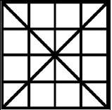
Classical Optical Distortion - occurs when the design of the optics or
image intensifier tube causes straight lines at the edge of the field of view to
curve inward or outward. This curving of straight lines at the edge will cause a
square grid pattern to start to look like a pincushion or barrel. This
distortion is the same for all systems with the same model number. Good optical
design normally makes this distortion so low that the typical user will not see
the curving of the lines.
Fiber Optics Manufacturing Distortions Two types of fiber optic
distortions are most significant to
Night Vision
devices:
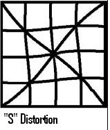 S-Distortion:
Results from the twisting operation in manufacturing fiber-optic inverters.
Usually S-distortion is very small and is difficult to detect with the unaided
eye.
S-Distortion:
Results from the twisting operation in manufacturing fiber-optic inverters.
Usually S-distortion is very small and is difficult to detect with the unaided
eye.
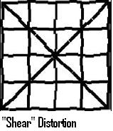 Shear
Distortion: Can
occur in any image tube that uses fiber-optic bundles for the phosphor screen.
It appears as a cleavage or dislocation in a straight line viewed in the image
area, as though the line were “sheared.”
Shear
Distortion: Can
occur in any image tube that uses fiber-optic bundles for the phosphor screen.
It appears as a cleavage or dislocation in a straight line viewed in the image
area, as though the line were “sheared.”
Gen 0 and Gen 1 image tubes produce a certain amount of geometric distortion in the image. In Gen 2 and Gen 3 systems, geometric distortion is eliminated although it is possible to encounter some perceptible S- and Shear distortion. The degree of any distortion and its interference with the application should be considered. When the application involves photography, video work, or weapon sights, the distortion and peripheral resolution are critical. Some older and low quality tubes may have distortion of the viewed scene.
Weather Resistance- The ability of a Night Vision system to operate under adverse environmental conditions is another important factor. Any system built to U.S. Military specifications for environmental factors will perform suitably under almost any condition encountered. The ability to resist humidity and moisture can become critical.
![]()
 Tube blemishes (aka blems
or spots) are common in ALL image intensifier tubes. Image tubes are NEVER
flawless, and every tube will have blemishes to some degree. This is caused by
minute defects in the fiber optics or mixture on the photocathode. These
cosmetic defects in no way hinder the reliability or function of the system. The
fewer and smaller the blemishes, the better the quality and therefore the higher
the price. Tolerance of a few tiny
black spots keeps the price of NVD 's within reach. All our
Night Vision
Devices are tested for a wide range of performance standards, including screen
spots. Any screens outside of tolerance are scrapped.
Tube blemishes (aka blems
or spots) are common in ALL image intensifier tubes. Image tubes are NEVER
flawless, and every tube will have blemishes to some degree. This is caused by
minute defects in the fiber optics or mixture on the photocathode. These
cosmetic defects in no way hinder the reliability or function of the system. The
fewer and smaller the blemishes, the better the quality and therefore the higher
the price. Tolerance of a few tiny
black spots keeps the price of NVD 's within reach. All our
Night Vision
Devices are tested for a wide range of performance standards, including screen
spots. Any screens outside of tolerance are scrapped.
Automatic Brightness Control (ABC)
An electronic feature that automatically reduces voltages to the microchannel plate to keep the image intensifier’s brightness within optimal limits and protect the tube. The effect of this can be seen when rapidly changing from low-light to high-light conditions; the image gets brighter and then, after a momentary delay, suddenly dims to a constant level.Azimuth Quantities may be expressed in positive quantities, quantities increasing in a clockwise direction, or in X, Y coordinates where south and west are negative. They may be referenced to true North or magnetic North depending on the particular weapon system used.
These are cosmetic blemishes in the image intensifier or can be dirt or debris between the lenses. Black spots that are in the image intensifier do not affect the performance or reliability of a night vision device and are inherent in the manufacturing processes. Momentary loss of the Night Vision image due to intensifier tube overloading by a bright light source. When such a bright light source comes into the night vision device’s view, the entire night vision scene becomes much brighter, “whiting out” objects within the field of view. Blooming is common in Generation 0 and 1 devices.Bright-Source Protection (BSP)
An electronic function that reduces the voltage to the photocathode when the Night Vision device is exposed to bright light sources such as room lights or car lights. BSP protects the image tube from damage and enhances its life; however, it also has the effect of lowering resolution when functioning. The unit of measure used to define eye correction or the refractive power of a lens, equal to the reciprocal of the focal length in meters. Usually, adjustments to an optical eyepiece accommodate for differences in individual eyesight. Most Night Vision systems provide a +2 to -6 Diopter range.Elevation The vertical distance of a point or level on, or affixed to, the surface of the Earth measured from mean sea level
A steady or fluctuating pinpoint of bright light in the image area that does not go away when all light is blocked from the objective lens. The position of an emission point within the field of view will not move. If an emission point disappears or is only faintly visible when viewing under brighter nighttime conditions, it is not indicative of a problem. If the emission point remains bright under all lighting conditions, the system needs to be repaired. Do not confuse an emission point with a point light source in the scene being viewed. The distance a person’s eyes must be from the last element of an eyepiece in order to achieve the optimal image area. Image intensification tube specification used to qualify exportability. Calculated on resolution (line pairs per millimeter) x signal-to-noise. A faint hexagonal (honeycomb) pattern throughout the image area that most often occurs under high-light conditions. This pattern is inherent in the structure of the microchannel plate and can be seen in virtually all Gen 2 and Gen 3 systems if the light level is high enough. A unit of brightness equal to one foot-candle at a distance of one foot.MIL. A unit of angular measurement equal to 1/6400 of a circle
Reticle A mark such as a cross or a system of lines lying in the image plane of a viewing apparatus. It may be used singly as a reference mark on certain types of monocular instruments, or as one of a pair to form a floating mark as in certain types of stereoscopes.
Tritium Dot A radioactive isotope that glows in the dark, mounted on the front sight
THE METRIC SYSTEM AND EQUIVALENTS
Linear Measure1 Centimeter = 10 Millimeters = 0.01 Meters = 0.3937 Inches
1 Meter = 100 Centimeters = 1000 Millimeters = 39.37 Inches
1 Kilometer = 1000 Meters = 0.621 Miles
Weights
1 Gram = 0.001 Kilograms = 1000 Milligrams = 0.035 Ounces
1 Kilogram = 1000 Grams = 2.2 Pounds
1 Metric Ton = 1000 Kilograms = 1 Megagram = 1.1 Short Tons
Liquid Measure
1 Milliliter = 0.001 Liters = 0.0338 Fluid Ounces
1 Liter = 1000 Milliliters = 33.82 Fluid Ounces
Square Measure
1 Sq Centimeter = 100 Sq Millimeters = 0.155 Sq Inches
1 Sq Meter = 10,000 Sq Centimeters = 10.76 Sq Feet
1 Sq Kilometer = 1,000,000 Sq Meters = 0.0386 Sq Miles
Cubic Measure
1 Cu Centimeter = 1,000 Cu Millimeters = 0.06 Cu Inches
1 Cu Meter = 1,000,000 Cu Centimeters = 35.31 Cu Feet
Temperature
5/9 (F - 32) = C
212° Fahrenheit is equivalent to 100° Celsius
90° Fahrenheit is equivalent to 32.2° Celsius
32° Fahrenheit is equivalent to 0° Celsius, 9/5 C +32 = F
APPROXIMATE CONVERSION FACTORS
| Change | To | Multiply By |
| Inches | Centimeters | 2.540 |
| Feet | Meters | 0.305 |
| Yards | Meters | 0.914 |
| Miles | Kilometers | 1.609 |
| Sq Inches | Sq Centimeters | 6.451 |
| Sq Feet | Sq Meters | 0.093 |
| Sq Yards | Sq Meters | 0.836 |
| Sq Miles | Sq Kilometers | 2.590 |
| Acres | Sq Hectometers | 0.405 |
| Cubic Feet | Cubic Meters | 0.028 |
| Cubic Yards | Cubic Meters | 0.765 |
| Fluid Ounces | Milliliters | 29.573 |
| Pints | Liters | 0.473 |
| Quarts | Liters | 0.946 |
| Gallons | Liters | 3.785 |
| Ounces | Grams | 28.349 |
| Pounds | Kilograms | 0.454 |
| Short Tons | Metric Tons | 0.907 |
| Pound-Feet | Newton-Meters | 1.356 |
|
Pounds per Sq Inch |
Kilopascals | 6.895 |
| Miles per Gallon | Kilometers per Liter | 0.425 |
| Miles per Hour | Kilometers per Hour | 1.609 |
| Centimeters | Inches | 0.394 |
| Meters | Feet | 3.280 |
| Meters | Yards | 1.094 |
| Kilometers | Miles | 0.621 |
| Sq Centimeters | Sq Inches | 0.155 |
| Sq Meters | Sq Feet | 10.764 |
| Sq Meters | Sq Yards | 1.196 |
| Sq Kilometers | Sq Miles | 0.386 |
| Sq Hectometers | Acres | 2.471 |
| Cubic Meters | Cubic Feet | 35.315 |
| Cubic Meters | Cubic Yards | 1.308 |
| Milliliters | Fluid Ounces | 0.034 |
| Liters | Pints | 2.113 |
| Liters | Quarts | 1.057 |
| Liters | Gallons | 0.264 |
| Grams | Ounces | 0.035 |
| Kilograms | Pounds | 2.205 |
| Metric Tons | Short Tons | 1.102 |
| Newton-Meters | Pound-Feet | 0.738 |
| Kilopascals |
Pounds per Sq Inch |
0.145 |
| Kilometers per Liter | Miles per Gallon | 2.354 |
| Kilometers per Hour | Miles per Hour | 0.621 |
![]()
Home | Contact Us | About KERIF | Export Regulations | How to Order

![]()
(702) 324-6463 / (702)
869-8451 FAX
sales@nitevis.com or kerifnightvision@earthlink.net